09 March 2021
MCM is a specialist in the design and production of flexible manufacturing systems. The core of them are 4 and 5-axis horizontal machining centres, characterized by technical solutions to achieve maximum performance with no compromises. In addition to the units manufactured at our facility, MCM is also able to incorporate, into the production lines, machines featuring complementary technologies. This allows the engineering of complete and customized solutions, giving customers the benefit of a single, competent and reliable partner. MCM’s product range includes machining centres, flexible automation solutions, systems integration, management software and process technology.
Aeronautical engine manufacturer for over 110 years, Safran, through its subsidiary Aircraft Engines designs, develops, produces and markets, alone or in cooperation, engines for civil and military aircraft, as well as for satellites. This activity is based on a clear vision of the market, unique expertise, world-class industrial capabilities and a full range of services to optimize engine maintenance and fleet management. Faced with the challenges of a growing aviation market, Safran Aircraft Engines prepares for the future and anticipates the needs of its customers, by investing continuously in the development of new technologies and designing ever more environmentally friendly engines.
THE TECHNOLOGICAL CHALLENGE
Safran Aircraft Engines found itself faced with a significant new technological challenge in the production of new aerospace components in advanced materials, including the turbine discs for the LEAP engine, the engine produced and marketed by Safran Aircraft Engines and GE within CFM International.
The necessary throughput and volumes of components had become significantly greater than that which the previously installed system, composed of a series of vertical lathes and horizontal-axis machining centres connected by wire-guided shuttles, was able to provide.
The original system did not offer the flexibility imposed by the new requirements and involved significant transfers of semi-finished parts and extensive use of floor space.
The new fan casings for the LEAP motor are made from a nickel alloy with advanced mechanical properties, including its high structural strength even at very high temperatures, typical of the interior of jet engines. This characteristic, however, limits the material’s ductility. The alloy stays strong at the cutting temperatures developed during material removal, but the poor thermal conductivity leads to a concentration of heat at the tool-swarf cutting face, as well as causing significant stress and wear in the inserts caused by chemical diffusion. The machines previously installed at Safran Aircraft Engines were not suited to the machining of the new material; the maximum pressure of the coolant supply at the point of machining, which was around 5-10 bar was insufficient for adequate material removal and evacuation of the swarf.
The spindle torque was also too small for the demands of the material used. The high level of force required for material removal also causes significant mechanical stress in the components being machined. In the case of fan casings, which feature particularly thin walls, the risk of permanent deformation of the component is very high. As such, the most significant technological challenge was to develop a correct machining strategy. This required a dedicated analysis of the machining cycle, including the clamping, the cutting parameters and positioning in order to allow the balancing of the tension and mechanical stress on the workpiece in order to prevent its deformation.
MCM, in complete synergy with the customer, developed a dedicated solution to all technical hurdles encountered in the Safran Aircraft Engines turbine disc production line.
The customer was partnered in the construction and fitting out of a new specific industrial building for this production line, which included generating a virtuous flow of technical information which was both fundamental for the customer and functional to the optimised management of the new system and the production processes.

MCM PRODUCTION SYSTEM
To date, MCM has supplied 12 machining centres set up as three FMS lines. Each composed of four Tank 1600 machines. These machines are multitasking, and are capable of combining milling and turning operations: this optimises the layout of the production site, reducing the number of machining operations and the flow of semi-finished parts in transit. These are all crucial aspects in reducing the cycle time and with it the associated production costs.
The structure of the Tank 1600 offers a high level of rigidity, making the machine extremely tough (strong resistant) and is able to support both the significant cutting forces and the inertia due to the high level of dynamics designed into the machine.
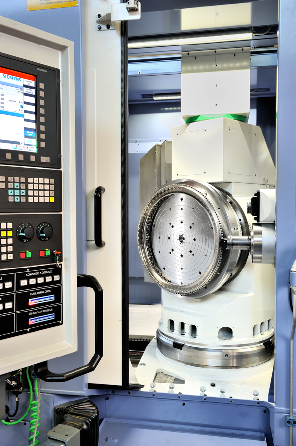
To undertake a revolutionary machining strategy, an unusual characteristic of the installed machines is the presence of a system known as a”5-axis vertical table”; this is installed on the rotary table and is able to position the workpiece & the pallet as part of a group with a horizontal rotation axis. This also optimises the turning operations and provide ideal swarf removal from the component. Integral to the 5-axis vertical table is the spindle, which allows turning operations of up to 500rpm.
This solution has led to the adoption of an exclusive 45° pallet change system, which is able to take the pallet from the FMS (where the pallet is horizontal) and position it vertically in the working area of the machine, with a horizontal rotation axis.
The milling electro spindle features a power output of 60 kW, with 8000 RPM maximum speed and 487 Nm maximum torque with an interface of Capto C8.
It is fundamentally important to delivering the correct pressure of coolant at the cutting face; to enable remove swarf removal, protect the cutting tool and most critically, the component being machined. As a result, a high-pressure coolant system was provided and allows pressures of up to 250bar to be achieved during the turning operations.
This pressure guarantees an optimum cooling for the cutting operations and reduces the friction phenomena leading to the limited wear resistance of the inserts, thus minimising the impact of tools on the overall costs.

This solution has led to the adoption of an exclusive 45° pallet change system, which is able to take the pallet from the FMS (where the pallet is horizontal) and position it vertically in the working area of the machine, with a horizontal rotation axis.
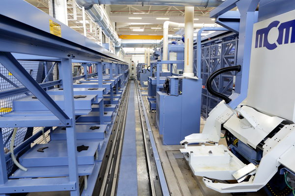
The operator stations offer the possibility to dynamically balance and centre the workpiece before it enters the production system; this is possible thanks to high-precision bearings and control systems, as well as a dedicated component loading station, including electric tools for the workpiece fastening. All these solutions reduce and eliminate chatter caused by unbalances in the workpiece when the component is being turned and prevents abnormal stresses in the machine, the cutting tools and, more generally, a significant decrease in rejected parts. The machining centres are strategically aligned in such a way as to share pallets and tool storage options, and this allows maximum production flexibility (ability to offset and redistribute machining operations between the various machines) and avoiding the need to duplicate tools and resources for each machine, thus optimising running costs. Each machine is able to access a total of 597 tools from the shared tool storage.

32 pallet stores over two levels and the three machine MCM TANK 1600 cell, has to all 597 tools from a shared tool storage carousel.
Each component of the system, from the tools to the equipment and accessories, is managed by special functions and dedicated software. The jFMX supervisor, software developed by MCE, MCM’s IT division, operates at a higher level. The jFMX supervisor provides real-time co-ordination and management of all the system’s functions and resources and is constantly processing an enormous quantity of field data. In this manner, it not only manages the system but also supplies a range of information and statistics on the productivity, efficiency and availability of the entire FMS. In other words, it fully responds to the essential principles of Industry 4.0. This information is key to understanding production trends, optimising resources and carrying out predictive maintenance, as well as minimising machine downtime and ensuring the highest levels of efficiency.
For a copy of the case study, please click here to request a copy:
WORKING VOLUME
X-axis 1,600 mm
Y-axis 1,010 mm
Z-axis 1,400 mm
Rapid feeds 50 m/min
Thrust 2,000 daN
Linear axes measuring system Heidenhain pressurised optical scales
Circular axes measuring system Heidenhain pressurised encoders
Linear axes positioning precision VDI 3441
Positioning precision (P) 6 µm
Positioning repeatability (ave Ps) 3 µm
Circular axes positioning precision VDI 3441
Positioning precision (P) 6 ”
Positioning repeatability (ave Ps) 5 ”
Spindle
Attachment Capto C8
Rotation speed 8,000 RPM
Maximum power 60 kW
Maximum torque 487 Nm
Front bearing diameter 110 mm
“Mirror” tool magazine
Total capacity Approx. 600 tools (for each pair of machines)
Tool type Capto C8
Maximum tool length 500 mm
Maximum tool weight 25 kg
Tool preset station Tool renewal while the machine is running
Pallet magazine
Pallet dimensions Ø 800 mm
Fixture & workpiece diameter 1,100 x h 400 mm
Maximum load allowed on pallet 600 kg
Total capacity 32 pallet stores over two levels (for the first 2 machines)
Operator station 1
Continuous rotary table (B axis)
B-axis positions 3,600,000
Turning spindle
Rotation speed (milling) 100 RPM
Rotation speed (turning) 500 RPM
Maximum power 77 kW
Maximum torque 2,600 Nm
Integrated customized options
Workpiece balancing system At the operator stations (managed by jFMX supervisor)
Semi-automatic workpiece screwdriver At the operator stations (managed by jFMX supervisor)
High-pressure coolant system 80 bar milling / 250 bar turning
Global FMS supervisor and options JFMX
Other MCM Links:
Sign up for updates